martes, 14 de julio de 2015

Engine Management in F1

The idea of  this post is based of this great blog AlbrodpulF1 , in the post technical analysis  of power units architecture of F1 .

In the APPENDIX 3 POWER UNIT ENERGY FLOW

With this energy flow we can see two configurations in the Power Unit.

Acceleration configuration.

All energy of car is provided to wheels, therefore ICE crankshaft by MGU-K and pressure in the air inlet with MGU-H


Brake configuration.

Power Unit try to recover energy brake, MGU-K increase the engine brake and MGU-H extract energy of air flow of engine.


ERS Limitations.

The problem is the limited the energy flow
  • 4MJ/lap give with MGU-K
  • 2MJ/lap recover with MGU-K
  • 4MJ maximum in Energy Store
  • 120kW MGU-K  as motor or generator
  • 125,000 rpm max in the MGU-H
MGU-K is limited its energy to recover with 120kW is 16.7sg to recover and 33.3sg to provide power.

Therefore if we want recover the 4MJ/lap you need recover 2MJ/lap with MGU-H y you exceed the energy you can to drive to MGU-K or MGU-H and it must manage the energy flow.

How manage the energy flow?


The best way to understand is with examples.


Acceleration with MGU-H low rpm.

Used the energy store to apply power MGU-K and MGU-H

Acceleration with MGU-H high rpm.

Used exceed pressure energy in the turbo to provide energy to MGU-K and therefore engine save energy in Energy store, and this energy doesn’t count to 4MJ/lap, therefore we have more energy available, provided by turbine.


Brake.

Without restrictions, all energy goes to Energy Store.

Brake with exceed 2MJ/lap exceed in MGU-K, and MGU-H with low rpm

We can to use the energy to MGU-K energy to increase rpm in MGU-H as flywheel, and the Energy flow between MGU-K and MGU-H don't have restrictions.


Brake with exceed 2MJ/lap exceed in MGU-K, and MGU-H High rpm or Full energy in store

We can to use the energy to MGU-K energy to increase rpm in MGU-H and this increase the charge in the compressor.

Compresor energy flow

With restrictions of rpm in the MGU-H we can keep rpm with two ways:
  • Relief valve in the turbine to discharge pressure.
  • Increase the works in the compressor.
The compressor works (Air Flow is blue arrows):
  • P1 and T1 is the environment.
  • P2 and T2 is increasing for compressor
  • P3 is the same but and T3 is decreasing in the intercooler
  • If we suppose P4 is environment pressure T4 is lower than environment temperature, and we can to use to cooler other ancillaries as electronics or engine, and this lets have less cooler inlet in the car.

 
Therefore we can to use the exceed energy/air flow to coolant other parts in the engine, and this let smaller radiators.


martes, 2 de junio de 2015

Camber thrust in motorbike

In every driving school for turn always it show the same image, when you turn, you must to lean the motorbike to equilibrate forces, where α is the lean angle.


The lean angle is angle between line Center of Gravity (CoG) and contact patch the vertical vector of gravity 


Theory of CoG displacement


In motorcycle racing, leaning the torso, moving the body, and projecting a knee or elbow to the inside of the turn relative to the bike.


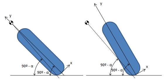
This create a effect of displacement of  CoG, in the next figure, we can see 

For the same speed in the same turn α (lean angle) must the same to equilibrate forces. But with the Cog displacement the α' (banking angle) of motorbike, it doesn't necessary the angle

And the displacement of CoG is more close to tarmac (less in y axis) and external (more in x axis) of middle of motorcycle,  α' (banking angle) is minor.

The typical explanation of this effect is mechanic, α' (banking angle) is limit in the motorcycle, the motorbike have a limit of the α' (banking angle), if you increase the difference  α - α' value, you can pass more quick in the turn with the same α' (banking angle).


But this theory have one error, and this is the relationship of between weights. 

If we make easy exercise with weight ratio,  motorbike is 180kg, and pilot is 70kg, if the CoG is the same point in the circuit straight and pilot wants move overall CoG 1mm, the pilot must displace her CoG 3.57mm.


Therefore exchange the mechanic limit of α' baking angle motorbike to pilot, and the pilot touch tarmac and motorbike is able of turn more. I am sure that this image is reminded for a lot of people. 


In this moment the limit es the pilot and the bike follow the turn, because touch with the other part lose the wheels.

I dont say that this action in the pilotage is wrong, I say that this explanation is not really true.

Theory of rolling cones

If we return the basic equation, we can see that the angle is equilibrium forces.


Ans the RTurn is the radius of turn


If we suppose the wheel without deformation rear wheel 190/55R17 and front wheel 120/70R17.

But the wheel the radius cone is not radius wheel, this increase with the radius of wheel profile, and if we suppose this radio as rWheel


Hence if we compare the α' Bank angle and α Lean angle we reach this data


We can see that the turn radius is not same the mechanic for cones and equilibrium forces. If we want the same turning radius, or we change the gravity constant (increase for less lean angle necessary), or we displace the CoG. It is easier displace the CoG.


Cone semiangle is the same of  α' banking angle, therefore if we displace the CoG, we can increase the cone radius and we can approach the rolling cone radius to equilibrium forces radius. and we need correct with the difference  α - α' value


The problem is the high difference between angles, cone needs low angle, and for this reason the camber angle in the wheel car when it turns, the angle is low.


martes, 12 de mayo de 2015

Electric Motorcycle Premoto3 (is a moto3 but other engines)

This is a project that I have in my mind.

Motostudent in the 4th edition, participate is kind bike, but several circumstances, (to be daddy :), it is one of those ), I don't participated with UPM - Motostudent.

Maybe I am going to make this project in the future.

Now I present my project in several slide.
Title

Parts

Suspension

Brake, (the important is use the brake engine)

Synchronous Engine is the key

Synchronous engine/generator behaviour 

Batteries technologies

Technologies compare

Handicap of electric vehicles

Energy in one race.

Energy in one race

Energy in one braking

Energy behaviour in acceleration, keep speed braking and new acceleration

Energy flows in acceleration, keep speed braking and new acceleration

Current Technologies

Ultracapacitor behabiour with V =cte charge

Ultracapacitor efficiency
Reasons for select capacitance. 

Planning for energy necessary for one race.

Energy diagram

Energy diagram in acceleration

Energy diagram in braking

Wiring diagram
Of course if someone wants to carry out this project, he will have my support.