Mostrando entradas con la etiqueta ERS. Mostrar todas las entradas

viernes, 22 de septiembre de 2017

Efficiency​ in Power Unit in F1

Following the post Engine Management in F1 and Mercedes new about achieve more 50% efficiency  in F1 engine, I want show my opinion about this milestone.


In this post I suppose that we know how works the ICE (Internal Combustión Engine) with its four times

ICE otto cycle 

In a ICE with turbo compressor, the compressor increase the pressure into the combustión chamber in inlet time.

Turbo compressor layout

The turbo is designing to increase the ICE power, but in the case in F1 this is linked to  MGU-H, and this is a electric engine, one point to remenber into de turbo is that rpm is "proportional" to inlet pressure.

In several webs show the MGU-H like one system to mitigate turbo compressor behaviour that it is knew like Lag turbo.


One summary about lag turbo is, when engine works low load, the rpm in turbo and compressor is low because dont need more pressure to provide power.

But when we need power, engine pressure is low and we need increase this pressure with increase rpm in compressor, and this lag is the time that turbo exchange exhaust pressure in rpm. This rpm depend to pressure in exhaust gases, and when we have low pressure inlet ICE, we have  low pressure in exhaust (less air to burn less exhaust gases). Therefore we need to reach the rpm to increase the pressure in the compressor and this increases pressure in the exhaust, and this effect have a feedback, but this feedback have a lag time that it is measure in seconds (depend of the turbocompressor size).

Therefore in the F1, the MGU-H increases turbo compressor rpm with electric engine, and it doesn't have lag time.

Another effect that it is not explaining,it is works like electric generator too, if you keep turbo compressor rpm, although exhaust gases pressure try to increase this rpm, meanwhile extract electric energy.

Turbo shaft engine

Turbo shaft engine is one engine that use the same principle that ICE with turbo compressor, but the the power is not in the crankshaft, the power is transmitted to turboshaft (turbo compressor shaft)

This engines is used in airplanes and helicopters because the ratio weight/power is very low, and they are small.

TPE331

For example the TPE331, is a small engine, like motorbike engine, and reach between 700 and 1000 HP, like a F1 Power Unit, and normally turboshaft have more efficiency that ICE.


This version is more complicate and provide 1600HP with less maintenance


In this video we can see the size of TPE331


Turbo shaft in Formula 1

We can see the big reduction gearbox in turboshaft engine due to the rpm in shaft is very high, but in the MGU-H don't need the gearbox because we could design the electric generator to work at those rpm.

With the same principle, we could use the turbo compressor into the engine, an then like I exposed in the Engine Management in F1 , this power could be send to batteries or MGU-K.

The relationship between MGU-H and MGU-K is the  same behaviour tan gearbox in the turboshaft,but electrical relationship, therefore we could a mix engine Turbo compressor ICE and Turboshaft engine, and this relation doesn't be limited by energy regulation in Formula 1 (4MJ per lap).

How history we could to see the Chrysler Turbine have a car with Turboshaft like engine, and the problema was:
  • Maintenance, this engine works to high rpm and increase material wear, (remember this design in 1960 and they didnt have to current materials and the quality manufacture that we have today)
  • Consumption, this engine dont have Start-Stop and to máximum power have a great efficiency, in idle or mid load the consumption is high if we compare with ICE engines.
  • Overheat, extract the heat is one problem in this engines, now we have studies with the simulations, and could be resolve this problem with low speed air to cool if we compare against airplane or helicopter.
  • Rpm range to use the engine with best behaviour is  smaller than a ICE.
  • Noise, all people that live near of airport could be explain this inconvenence.

jueves, 7 de julio de 2016

Why the car electro is farthest from what it seems?

Independently of engine technologies, substitute engine must provide the same service that actual engines. The electric engine could be reach the power of ICE (internal Combustion Engine).

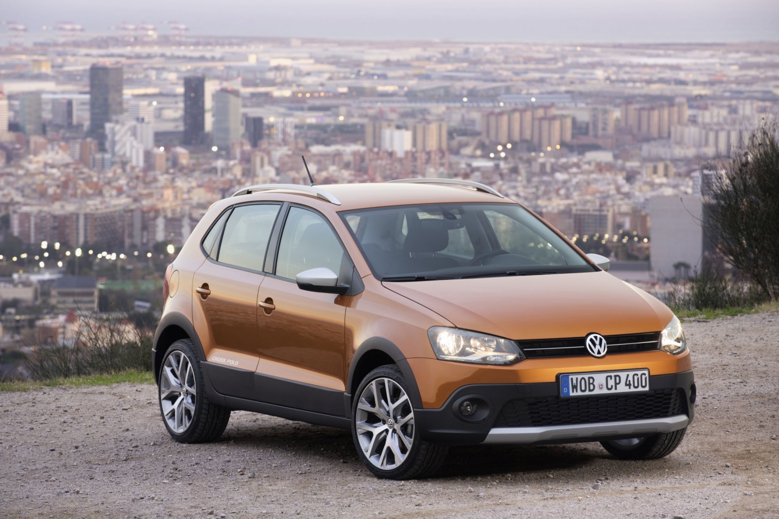
We take like base a VW Polo 1.2


  • Fuel consumption (town) 5.8 L/100km  
  • Fuel consumption (highway) 4.1 L/100km  
  • Average fuel consumption 4.7 L/100km 
  • Engine Power kW 81 kW
  • Average trip with full tank 1125 km (703 miles)
  • Weight 1163 kg

We need to compare with fossils fuels, mainly isoctane (petrol) that have 11,778 Wh/kg; 42.4 MJ/kg. but in this case we set efficiency around 30%.


Internal Combustion Engine
Pretol
Energy
42.4 MJ/kg
Density
0.748kg/L
η
30.00%
Consumption each 100 kms
4.10 L
100 kms
3.06 kg
Energy Consumption 100 kms (EPetrol)
129.9 MJ
Energy used in 100 kms (EPetrol η)
39.0 MJ


If we suppose 1,125 kms with constant speed without energy recovery possibility, we need (39MJ/100kms x 11.25kms) 438.56 MJ to move the car this distance and we could use this value like standard.

Batteries technologies 

BATTERIES
TECHNOLOGIES
MIN
MAX
Lead
30 Wh/kg
108 kJ/kg
40 Wh/kg
144 kJ/kg
Ni-Fe
30 Wh/kg
108 kJ/kg
55 Wh/kg
198 kJ/kg
Ni-Cd
48 Wh/kg
173 kJ/kg
80 Wh/kg
288 kJ/kg
Ni-Mh
60 Wh/kg
216 kJ/kg
120 Wh/kg
432 kJ/kg
Li-ion
110 Wh/kg
396 kJ/kg
160 Wh/kg
576 kJ/kg
Li-Po
100 Wh/kg
360 kJ/kg
130 Wh/kg
468 kJ/kg
Ultra Capacitor
7 Wh/kg
27 kJ/kg
7 Wh/kg
27 kJ/kg
Fuel Cell
14,400 Wh/kg
51,840 kJ/kg
33,333 Wh/kg
120,000 kJ/kg

If we take the best current batteries technology, it is the Li ion and  for use the 438.56 MJ we need 761.4 kg. This is the weight of current Polo.


Second problem is the mean life of batteries the batteries life is around 200 cycles of 2.5 years, (guarantee power > 90%). Several test show that the life is 8 years, and one packet batteries is $8,000-$12,000.


The other problem is the  manipulation conditions, the voltages maximum should not exceed 50-60V. Several regulations and mechanics without experience with high voltage electrical systems, we should think in secure manipulation for this workers.

Making numbers

Our model of Engine Power is 81 kW with 50-60V we need 1,620-1,350 A and the maximum power.


In the 1,125kms, if we suppose the constant speed 100km/h is 11.25h or 675 min or 40500 s, therefore if we use 438.56 MJ, the engine should provide 10.8 kW meanwhile we keep constant speed. 10.8 kW with 50-60V we need 217-180 A.


The losses in electric system mainly is heat losses to internal resistance:

The internal resistance of one cell is near of 0.03 ohms.


Range
1125 kms
438,6 MJ
Average Speed
100,0 km/h
Time
40500 s
Power for 100 km/h
10,8 kW
Voltage
50,0 V
60,0 V
Current
217 A
180 A
Internal resistance
0,03 Ω
Internal losses
1,41 kW
0,98 kW
12,99%
9,02%

The internal losses is a problem near of 10% of losses therefore, the efficiency is now  90%, but it is following 3 times more efficiency than ICE.


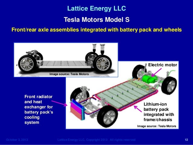
Everybody have contact with this fact, for example when we charge or use laptops, tablet, mobiles or smartphones... any PED (Portable Electronic Device) with batteries, we feel how it is heated, hence we can think, that cell packs need refrigeration systems in the electric cars, due to size.

Lattice Energy LLC slide
But we calculate with maximum power, the losses are increased exponentially.


Max power
81,0 kW
Voltage
50,0 V
60,0 V
Current
1620 A
1350 A
Internal resistance
0,03 Ω
Internal losses
78,7 kW
54,6 kW
97,20%
67,50%


However batteries, is a cell packs and depend how we make the packet


Each pack is compound by several cells
Cell element
3,7 V
12,00 Ah
0,25 kg
30,00 mΩ

 Cells is connected in serial and parallel circuit, and we can calculate more aproximation to real datas.
Cell pack
Series cells
14 S
17 S
Parallel cells
135 P
113 P
Num cells
1890 Cells
1921 Cells
Weight pack
480,38 kg
488,25 kg
Voltaje pack
51,8 V
62,9 V
Capacity pack
1620 Ah
1356 Ah
Ampere pak
1620 A
1356 A
Energy pack
302,10 MJ
307,05 MJ
Max Range pack
775 kms
788 kms
Power 1hour
83,92 kWh
85,29 kWh
Internal R Pack
3,11 mΩ
4,51 mΩ
Internal loses Max range
136 W
134 W
1,26%
1,24%
Internal loses Max power
8.165 W
8.299 W
9,73%
9,73%


We can see that the datas improve respect de last calculus, and efficiency is near 10%


Infrastructures problems


The other problems is civil installations, the electrical instalations for private use (homes).


The regulations expose mandatory near of 10kW instalations but the electrical services is not sizing for this power in all house. The Electrical Companies apply a simultaneity factors where, all consumers don't use together the max power. (this factor is important due to efficiency, if don't use near 100% of capacity, the efficiency is less)

Normally this simultaneity factor is near to 50%, and the service for electrical installations is for 5kW per house. Therefore the time to recharge is increased.

Recharge time
9kW
9h 19,4min
9h 28,6min
5kW
16h 37,3min
17h 54,2min


One solution for this problem is a Tesla Powerwall, for example where, it is charging all day and it provide the fast charge to car, when we need, like a power bank for a PED, or like a hidroelectrical dam. The problem is in each charge point need similar power that batteries car. Therefore the double batteries one in car and other in power bank (remember 760kg in lithium or 3 tonnes in lead-acid bateries).

World Lithium Reserve


This current estimate totals 28.4 billion kilograms Li, for one billion cars in the world, therefore is 28.4kg per each car, there fore this source (now mainly material for batteries), it dont have future.

Now is development other batteries technologies like Fuel cell, but now is expensive and need more development.

The future is electric car, however you dont await in next years. Maybe, the next decade.

martes, 14 de julio de 2015

Engine Management in F1

The idea of  this post is based of this great blog AlbrodpulF1 , in the post technical analysis  of power units architecture of F1 .

In the APPENDIX 3 POWER UNIT ENERGY FLOW

With this energy flow we can see two configurations in the Power Unit.

Acceleration configuration.

All energy of car is provided to wheels, therefore ICE crankshaft by MGU-K and pressure in the air inlet with MGU-H


Brake configuration.

Power Unit try to recover energy brake, MGU-K increase the engine brake and MGU-H extract energy of air flow of engine.


ERS Limitations.

The problem is the limited the energy flow
  • 4MJ/lap give with MGU-K
  • 2MJ/lap recover with MGU-K
  • 4MJ maximum in Energy Store
  • 120kW MGU-K  as motor or generator
  • 125,000 rpm max in the MGU-H
MGU-K is limited its energy to recover with 120kW is 16.7sg to recover and 33.3sg to provide power.

Therefore if we want recover the 4MJ/lap you need recover 2MJ/lap with MGU-H y you exceed the energy you can to drive to MGU-K or MGU-H and it must manage the energy flow.

How manage the energy flow?


The best way to understand is with examples.


Acceleration with MGU-H low rpm.

Used the energy store to apply power MGU-K and MGU-H

Acceleration with MGU-H high rpm.

Used exceed pressure energy in the turbo to provide energy to MGU-K and therefore engine save energy in Energy store, and this energy doesn’t count to 4MJ/lap, therefore we have more energy available, provided by turbine.


Brake.

Without restrictions, all energy goes to Energy Store.

Brake with exceed 2MJ/lap exceed in MGU-K, and MGU-H with low rpm

We can to use the energy to MGU-K energy to increase rpm in MGU-H as flywheel, and the Energy flow between MGU-K and MGU-H don't have restrictions.


Brake with exceed 2MJ/lap exceed in MGU-K, and MGU-H High rpm or Full energy in store

We can to use the energy to MGU-K energy to increase rpm in MGU-H and this increase the charge in the compressor.

Compresor energy flow

With restrictions of rpm in the MGU-H we can keep rpm with two ways:
  • Relief valve in the turbine to discharge pressure.
  • Increase the works in the compressor.
The compressor works (Air Flow is blue arrows):
  • P1 and T1 is the environment.
  • P2 and T2 is increasing for compressor
  • P3 is the same but and T3 is decreasing in the intercooler
  • If we suppose P4 is environment pressure T4 is lower than environment temperature, and we can to use to cooler other ancillaries as electronics or engine, and this lets have less cooler inlet in the car.

 
Therefore we can to use the exceed energy/air flow to coolant other parts in the engine, and this let smaller radiators.