miércoles, 30 de octubre de 2013

KERS I (Electric Generator/Motor)

The electrical generator/motor in the same machine is existing two types:
  • DC: The DC generator/motor has the problem of the efficiency and the pads wear, due to is brushed but very easy to make motor, due to only need a voltage.
  • AC synchronous  Is the best generator and the most efficiency, but have the problem of the synchronism, due to rpm of axis rotation is relation with the AC frequency.

How it works AC synchronous generator/motor

This is based in magnetic induction, and if we take the effect far as we are interested we have:

kv value is a function of the construction of synchronous machine. Normally the synchronous machine is triphasic, and it works with three phases and with a offset between phases of 120º degrees.


where:
  • a is a amplitude (it is 2E in the last formula)
  • b is a period, and it is depending of rpm

The machine generator through to motor if with the same signal that it creates for the machine, the E applied in the wires is higher than the generate by machine.

The synchronous machine have a several poles and coils, but if we have the triphasic, we have several coils that the induced current is equal.


If we compare with a batteries each coil, we can to make two type of connection, serial or parallel
  • Serial increase the voltage but keep the current
  • Parallel increase the current but keep the voltage

Normally for us it is more interest serial and increase the Voltage due to the wires have a internal impedance and the losses per heat are depending of the current that it pass through the wires, and the coils is assembled per long wires, therefore is more interested we have more voltage and less current.


The problem is if the voltage need more insulate and if we want to use like a engine, we need create higher voltage than the internal create per the synchronous machine.

AC generator

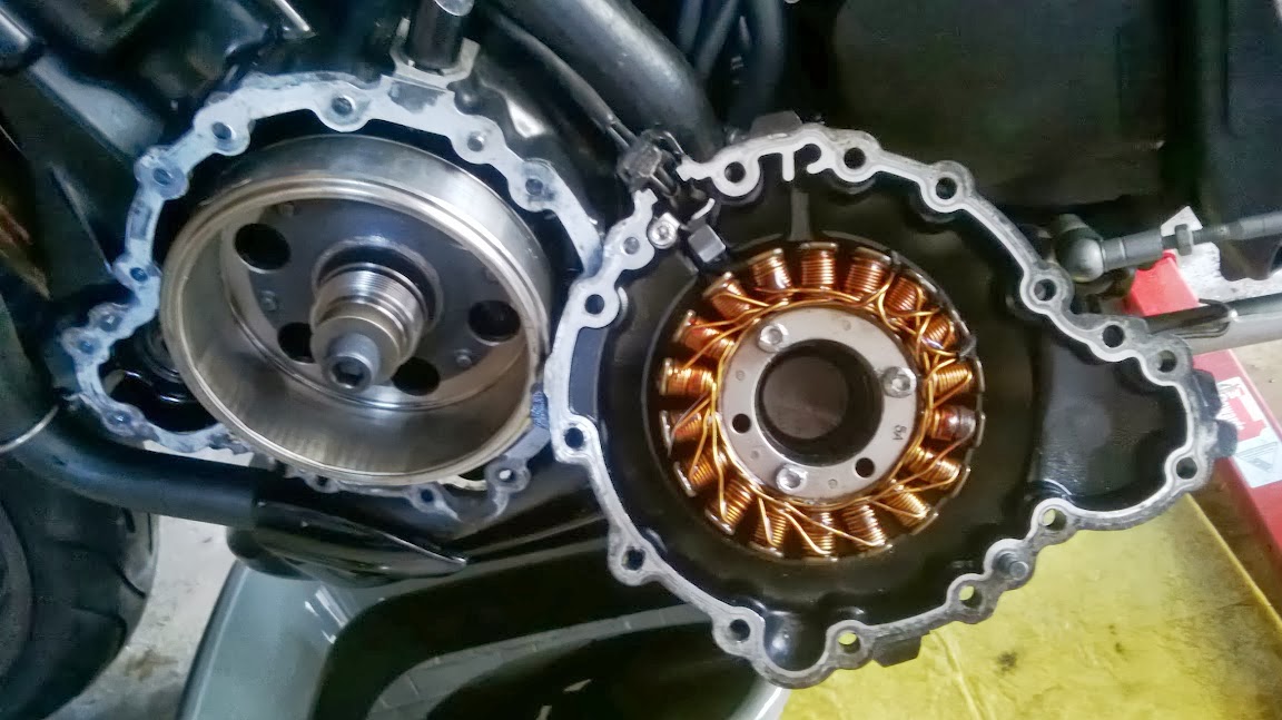
The typical construction is the coils in the stator and the magnet in the rotor, and with ne new magnets of rare-earth metals such as Neo­dymium

In this case if we have a high voltage is no problem cue to we can down the voltage with regulators, and theses are very simple and cheap to make.

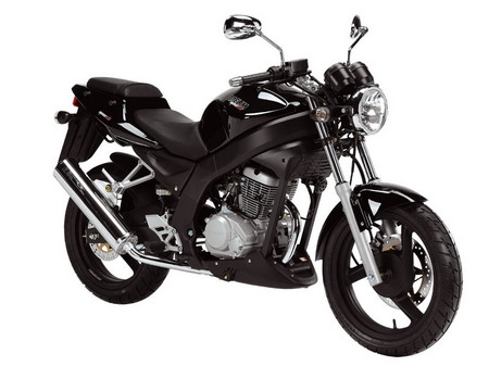
In the motorbike the generator is fixing to crankshaft normally.

For example the stator of 675cc engine of Triumph have a stator with 18 coils, arranged into 3 phases, and provide 30VAC minimum to 4000rpm. If we see kv value is 133, but for experience the good status of the the 30VAC is near to 2000rpm, therefore kv is near of 65, and near of 200W of Power.


AC engine

The synchronous machine as engine is the more efficiency machine and the most efficiency engine, (near of 95%), but it have two problems.
  • All voltages must be synchronous with the position of the rotor and the induction of the coils.
  • The maximum voltage to maximum rpm speed must be less voltage than the battery voltage

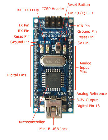
The problem of the voltages that it must be synchronous with the position of the rotor and the induction of the coils, it is solved by electronics, with the ESC (Electronic Speed Controller)


The circuit for one control of Brushless that I found in the web DIY Electric Car, Masina electrica ro

The voltage level is solve with the coils put in parallel, this increase losses in the wire, and down the efficiency, but it allow used a lot of batteries with low voltages.

This machine as a engine usually have a kv near of 1000, or more. The NTM Prop Drive Series 42-38 is a example with 750kv, Power 785W with 14.4V.


Synchronous Machine Generator/Motor

The best option is simulate the electronic gear box, where change the kv of machine, with the change the connection between coils and the batteries.

The Turnigy AquaStar T20 3T 730KV/1280KV Water Cooled Brushless Motor have the group of coils separated in A, B and C, and we can connect the coils in Y or Δ (V(Y)=1.73·V(Δ)).


  • Y provide kv = 730
  • Δ provide kv = 1280


Above of low rpm the connection of the coils are Y and when increase the rpm change the connection to Δ, for keep the voltage into of range.

Also it could use like:
  • Y as generator.
  • Δ as engine.
And the batteries don't have change the connection because the level of the voltage change by coils connection


In the Turnigy AquaStar T20 3T, we can see that we have limit the voltage near of 12V


But if use the usually kv for stator we have for example kv = 150 and the chart show that the limit of the voltage near of the 60V


If do to combine with the batteries or coils interchange connection serial / parallel, we can control for example, Stop and go, y the city with and save fuel and keep the temperature of the engine into of ranges, and part of low speed in electrical impulse, therefore with the save fuel, and creates the more efficiency combi-engines, electrical/gasoline, without a significant weight increase.

Other chances of system is we could to use in city circulation, when we are stop in the rush hour and the motorbike engine heat is increase, this system can to use as Stop and Go such as Audi or BMW, with several advantages:
  • Save fuel.
  • No bendix mechanism and no wear.
  • Keep the temperature into range.

In summer in the midday, in warm countries, into of the rush hour, several motorbikes stop inthe side of the roads due to the stop the engines by temperature, due to ECU cut off the engine to safeguard. This is normally in the stops and traffic lights.

Honda works in a new engine eSP for next-generation engines 125cc, and this engine use a this concept in their technology.

lunes, 7 de octubre de 2013

Air Navigation - Satellite Based Augmentation System (TCAS Low cost)

This project I send to ESNC (European Satellite Navigation Competition) in 2010, but the other projects were very good and I was not selected to follow the project.

However I think that this project is interesting and therefore I publish this post.

Description.

AN-SBAS works similarly at DME (Distance MeasurementEquipment) or SSR (Secondary Surveillance RADAR). , and the signal flight time, (t), provide to us the distance:


where c is the signal speed. (≈light speed).

The frequency in SSR, that use the systems such as TCAS, IFF, Transponder, is the 1030MHz for interrogation and 1090MHz answer signal. The systems interrogator send a "question" signal in 1030MHZ and the aircraft reply with any code, depend of the question emitted in the first signal.

If we have a GNSS coordinates with a 100m error, the time error is error/c.


into the aircraft we can readjust the internal clock time with the GNSS time and we have over  3e-5 seconds of error, (plus the system error).


If we synchronize the time UTC with satellite (GNSS) with the t transponder we can emit the signal synchronize in all airplanes, and we can see the distant between aircraft with the delay between the emit signal and the receive signal with a error is the equal to sum of DOPs of both aircrafts, and if we have 100m, the system show 200m of error. (This distance is very close)


Air augmentation (Transponder Update)

The range of this signal normally in aeronautical system is  250NM, the signal reach this range in 0.16 seconds, therefore we can emit and refresh the signal each 0.16 + between pulse.

For example 0.04 seconds of pulse, therefore 0.2 seconds, the system emit 5 times per second, and we allow that the each pulse no interference with previous pulse. Into the terminal area, the system can low the signal power, or it could to use another frequency to increase the refresh and the times per second.

The precision is increasing with the proximity, due to the atmospheric disturbances decrease, (inversely proportional), therefore the error decreases

t1< t2 the signal travels in the atmosphere minus time in t1 and therefore it has minus exposition to disturbances.


The idea of the system is create a volume of security, where if aircraft receives a signal in lower of previously selected, the system show a signal of the proximity traffic, and aircraft has directional antennas as TCAS antennas, it can know the emission radial such us a RADAR.


Ground update 

(DME)

Other advantage of the system is the coordination of the emissions, all planes send the signal in the same time, therefore rationing the electromagnetic spectrum  and this is one of problems with DME. the question have a poor regulation for it don't receive several questions in the same time, and each answer only one aircraft. If this system update DME it doesn't need questions and the answer provides information to all users of system.

The system is compatible  with the all system because if the DME could send the answer and one signal coordinate with the UTC, and without error due to the GNSS receiver of DME is static. The aircraft with the new DME system no question because recieve the answer UTC and clears electromagnetic spectrum for others airplanes with old DME system.


(TMA)

In airports and terminal areas with directional antenna, such as the VDF system, could mark distance with the AN-SBAS and direction with the arrays 

All airplanes sends the signal with synchronise with the GNSS time, the signal reach the VDF in the sequence  red, black, green and blue airplane. With the directional antenna, de VDF could know the direction of the signal, and read the position respect to him

The problem with the signal is the signal between airplanes very closes, could appear as one airplane, but the signal is with a pulse determinate, the VDF could recognize this error, or compare the other signal transponder with information with SSR. Also if we put other VDF in other points of the airport, they compare measures between them, and they could resolve this problem.

The airplanes could mark the relative position between theirs, with the antennas such as ADF antenna, or other directional antennas. This signal if we use PSK codification or digital FM, we can use de Doppler effect for more information, with this signal we can use the signal no only to know the distant, with Doppler, we can know the speed respect us. The speed between aircraft could measure with several pulses, but the Doppler provide more precision, because 10m/s cause increase o decrease the signal about 3.4KHz.


If the case in which use standard words with X bits, for example 12 bits, (SSR standard), if the system repeat 5 times this signal, we can through Doppler if the signal is 0.04s the signal time read for other airplane, change the time reception
And if we know the time emission and we can detect changes of the 1e-9 seconds the can read speed Doppler, of the 7.5m/s


The improves with the Doppler system, is the best relative speed measure, and this parameter is important due to if the relative speed is constant, if we maintain the path and the speed, when we will cross the paths we will crash between us. This system provides TCAS operation.


Into the terminal area where we have a increase of the airplanes density, the controller we have a better control with this system if use VDF system, this system provides direction of the airplanes and the time provides distance.

In a future DGBAS provide integrity between ground segment, and air segment, due to the DGBAS could read the position the airplane while it is landing.


Adventages of AN-SBAS.

The system is based in the time GNSS, however, the system send a message, and this message could send GNSS localization data, and this system can create a other airplane based augmentation system between them.

In Terminal area, if the AN-SBAS send the signal, and in ground use VDF, (VHF Direction Finder), (direction detector signal but in our case will be L band (LBDF)), this system with 2 VDFs could detect deviations in signal GNSS and provide to each airplane our correction or zone correction such as GBAS (Ground Based Augmentation System).

The correction for each aircraft would be to provide in landing stage, more focus and eliminate radiofrequency contamination in other areas, and it provide high accuracy, reliability of the other air navigation systems

Respect to integrity and availability, in terminal areas  we could be ground system o fixed or mobile, (Car, UAS, balloon fit in ground), for check the system, and into de AN-SBAS. The system can have satellite’s emulator based in ground, such as NAV aids, for example the atomic time send the signal in HF, MF and LF (long range), and this signal we can to use for integrity of the system, because is in static coordinates, and can provide Integrity signal for GNSS signal, (if I know my coordinates an the coordinates of the other transmiter I know the time of flight the signal,  and if this doesn't fulfill the system have any error)

The availability, with GNSS and the atomic time are global, therefore the system has availability with integrity global.

Electromagnetic spectrum are a problem today, therefore we need new systems that improve our spectrum with a reasonable prices and technologies. Today we use the same concept navigation systems since 1950, and for reason of the reliable and available, we still use this system. The problem of this system, although manufacture technology has changed, is the concept. Today all navigation systems can operate same with GNSS, and reach new capabilities.

The AN-SBAS, is complementary for navigation system, and simplifies and augment TCAS system, for more uses, such as instrument landing, navigation, SSR control. The difference is use the time satellite to synchronizes the pulse that transponder send, therefore it provides us distance measure.

This system update several navigation concepts, and this new system is cheaper to manufacture and calibrate and monitored, due to the other systems of navigation, this need expensive calibration. For example VOR, that the calibration needs to deploy test airplanes. This system only needs the onmidirectional antenna cheaper with more MBTF that other special antenna, such as VOR or ILS antenna.
This system are smaller than substituted systems and it can use others part of others system, for example GNSS antenna in ARINC 429 or NMEA. This is translating in less weight and therefore less consumption fuel, (in air's segment).

miércoles, 18 de septiembre de 2013

Control systems and the 4th and 5th generation fighter

The fighters 4th o 5th generation have in common several skills.
  • Stealth.
  • Super cruise.
  • Super agility.
  • Full equip digital electronics and communications.

In this post where I try to analize the relationship of two points that have this fighters
  • Super agility.
  • Digital electronics.

Introduction

Since 1960 the electronics development is on fire, the seed is in the WWII but the increase of the develop is in the 1960 with the Space Race, when change the electronic valves for the silicon technology.

The third stage of this rocket is the domestic electronics, PC, FPGA, systems, that it allow that and people could develop a lot of technologies, and with internet share with the rest of the world. (iOS and Android mainly is develop for the users)


Application in fighters

The electronic techology is applying in all fields of the fighter such as RADAR, ECM, weapons, navigation, .... and Flight Controls System (FCS).

The first step of FCS is in the F-16 like fly by wire. This system limit the actuation the of the pilot, and always system is into of the flight envelopes.

The system show some great potential, FCS is more precise than human pilot and it can flight into the limit envelopes that the pilot could not flight.


This introduce the Super agility


The base of control of flight by design is:

More stable less agility, but increase the agility the system may be can unstable.

For definition with point of sight of flight we have 3 cases
  • Stable: The airplane try to keep a flight straight and balance, if you extract the airplane of this profile of flight and then you free controls the airplane try to come back the same straight and balance that it had before. This is to seek for airline airplane or cargo airplane.
  • Neutrum: if we follow the example, the neutrum airplane when you free controls the airplane don't try to come back the same straight and balance, and this new position is the new "stable" position. (this is not practical due to is only a point of the control field and always the systems are stable or unstable).
  • Unstable: it is Super agility, the airplane don't like flight straight and balance, always try turn and this provide a lot of agility, and unstable have the properties of the "Caos theory" try turn but depend a lot of varibles of the radius turn, and this turn is erratic, and this provide a unpredictable path, and this complicate form example a missile computers and try to follow and destroy.

I can see that the unstable airplane will be a good fighter.

For example of a unstable is the same when we try to keep equilibrium a vertical broom in above of our hand.


This for a human pilot could be stressing, or imposible, for example the Eurofighter or a flight straight and balance, it needs 200 corrections per second, therefore the FCS is mandatory, beause the human pilot can't flight the airplane without this aid.

The problem of the unstable system are two, our electronic control is necesary and the error isn't pardonable.
  • The electronic fault of our computer is solve for redundance, with several control systems in parallel, and monitor system.
  • The nature of the unstable can't change, therefore only we can design a good and robust system without problems

The last is easier to say than to make.

As I marked before, the unstable behaviour have properties of the "Caos theory", and the system control theory only can control if you knows the system perfectly. Therefore if the system don't have the behaviour that we expect, we have a problem, we can see any examples.

  • The SAAB JAS39 Gripen had an accident in a Stockholm Air show due to FCS fail, and into out of control envelope flight.


  • The press presentation of F22 Raptor, due to the FCS can't correct the ground effect without gear deployed.
  • Arianne V fail in the first launch, due to the control (Arianne IV control) can't control the launcher
  • When our smartphone or dishwasher hangs is beacause the system control into in any part unknow for them, but you make a reset, and all problems are solved, but in airplane is more critical.
    In the stable airplane we pilot could flight due to the air planbe follow stable and the critical time to act is minutes, in unstable the time to act is millisecond, and the inputs must be into of a tolerance very small. The problem of the actuation in system unstable
    • Time to response, unstable system are very quick, for that we chose this system
    • Force to response, we have actuator for control unstable system, but this only can control into of limit envolope. For exampe, into of tha stall we knows perfectly the actuation the airplane, but the control surfaces barely have effect.
    • Knows to response, all this ever system knows and acting well, and this could provide problems source.
    Operation of control system The operation of the system is very easy, and very difficult too. The easy part is understand that system is a box where I introduce one input and receive one response, which it could depends of the other inputs and previous inputs.
    For example, we have one system and we want that the value of system output will be 10. We are controlling the inputs, and we shall put a several values in the input for the output is 10. Our system only multiply the input for 2
    Therefore our control system knows this and if we want a 10 in the system the control take our desired 10 and divide for 2.
    The problem is when the dinamic of the problem change:
    Our system think that our exit is 10 when in the real output is 12. Note This is a easy example, this type of error is very easy to correct with ouput monitor, but this want to show the error in the knowledge of system provides unknown exits, and it can follow the system out of envelope flight. Changes in the dynamics is very easy in one fighter, for example change of weapons configuration, but existed other types of unexpected changes, for example if the fighter have damages for a combat, and the system to control isnt easier than multiply for 2, for example the error of the F22 raptor, that it crash for only the control system are not awareness of the ground effect.
    Unstable airplane In flight if we have damages, normally the airplane increase the unstable nature, and if airplane have unstable nature may be any damages increase the unstable nature. The system unstable evolution, increase divergence between the initial point (our control point) and the next points that airplane follow. If we want keep the divergence to zero, and this we can get with our controls but the control have one problem
    We have the control very limited, and the normal the unstable system increase the K factor, therefore damages are going to limited our control or directly we cannot control de airplane, the controls have not effect. For example, if we follow the broom equilibrium and we make a sum of the forces, we have the inverted pendulum.
    The necesary force to keep the angle, is the same the weight of the pendulum multiply for tan of angle.
    • 0º the force F is 0N.
    • 26.56º the force F is middle of the weight the pendulum.
    • 45º the force F is the same of the weight the pendulum.
    • 63.43º the force F is double of the weight the pendulum.
    • 90º the force F is infinite.
    In this example I do not apply other forces such as inertia that incresase the force applied. Therefore, if the control system is in the limit of the control with knowledge of the airplane, if we introduce others values such as damages, the control system could not flight the airplane, due to system control cannot provide the enought force to correct the flight path. One example is the Eurofighter in Lybia, where the Tornado select the targets and the Eurofighter only flight like a bomb cargo. But RAF denies this idea. Obviously this article is only based in supposition without real and truthful information due to is this secret and it isn't published the algorithm of control, of test made for the controls.

    viernes, 13 de septiembre de 2013

    Arduino in Motorcycle

    First at all is that the english doesn't my mother tongle and may be sure I will make a lot of fails, but a one idea is this blog for practice me english, I hope that the reader apologize me those fails, and if you wish, mark this fails in the comments.


    I am a proud owner of DAELIM Roadwin FI and now I connect the system  based in arduino for show in one LCD screen based in OLED 0.96" "monochrome"
    The base code as drivers of the screen is https://learn.adafruit.com/096-mini-color-oled
    Therefore, I should send my greetings to all forumers and his information exposed in http://arduino.cc/forum/


    With this system I installed a system that it let me:
    • Temperature oil
    • Temperature enviroment
    • Clock
    • Voltage.
    When detected the low or over voltaje, this value blink, and temperature oil happens the same, when it see low or over temperature.


    The Arduino used is the Nano V3.0:
    The code is beta (it needs any improves):

     The Circuit of system is this:


    This is the display in the motorbike: